

|
Featured Developer
|
|||
|
|||
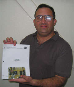 Here is the description of Tony Gonzalez's innovative use of the W65C134S UART.
At my main job, a work project was an automated test fixture that would take the company AV type product and run a series of tests. There are such machines on the marketplace. However, they are extremely expensive and tend to obsolete as the company's product line expands and improves over time.
The basic design goals were for a test fixture that would be usable for all products and be easily upgradeable for future products yet to be designed. To this end, the basic concept was a host computer which would run the testing cycles and a rack mount sized cartridge which would use a slave computer board and control various sub boards to do certain functions such as AV switching, media generation and control signals for the products being tested.
The first design used a single off the shelf type CPU experimenter's board. This quickly proved impractical as it was not capable of the quick design cycle or expandability required for the cartridges.
The second revision used the AT89C2051 with an I2C chain for the various sub boards. This also proved impractical as it was a pain in the neck to get things working correctly. The last straw for this design was that the chip is absolutely incapable of being an I2C slave, a fact very rarely mentioned.
I then made the decision and got the ok to do a design from the ground up for the board systems within the cartridges. The main controller board would be 65C02 based for several reasons:
1. Cost. The board design would cost less than half of the off the shelf units but it would be able to perform all the functions needed.
2. Support. I have been a member of 6502.org for some years and have spoken to WDC on occasion. I did not have experience with the type of chips used on the mass market board. I have been doing a pinball machine design based on 65C02 and the support is fantastic from everyone at 6502.org and WDC.
3. Ease of usage. I was far more familiar with the 65C02 family than the competition. I spent more time working around learning the competition and frankly, I was less than thrilled to work on it. It was a chore, with strange bugs and conditions.
WDC told me about their all in one chip, the 65C134 and urged me to give it a try. This chip is impressive. It is basically a 65C02 with a built in Monitor ROM with library, UART for RS232 serial communications, Serial Interface Bus (SIB) for local area networks, 4 ports and a ton of interrupts. Add in a Time of Day (ToD) clock and you have some serious power in single chip.
It turned out to be uncharted territory a little bit. I had ever used the chip before and didn’t want to use the WDC W65C134DB Developer Board, so I proceeded to read the WDC documentation and learning more about the W65C134S.
The more I learned about the chip, the better I liked it.
WDC was quite gracious in helping me over the learning curve needed. I made the decision to use TTL gating instead of a programmed CPLD (a Xilinx 95108 CPLD I used on WDC’s W65C134DB Developer Board). This was for 2 reasons.
1. Cost.
2. Education. I planned to share the experiences with this chip in an article on 6502.org.
The board was designed with onboard ROM and RAM and 8 slot connectors to control each function board within the cartridge. The 8 slot connectors ran from the peripheral ports. The board would take control signals from the host computer via RS232 lines. Once the board would receive the commands, it would act upon them, running each function needed. A small diagnostic was to place a CPU controlled LED onboard as part of the design. This was always my cheap debugger routine. I would flash the LED off and on to check parts of a program for proper function. For example, I could insert a call to the flash routine to see if a program made it to a certain point or got stuck. I was using Mike Kowalski's free assembler and a Tech Tools EPROM emulator 3. I could literally correct a mistake in code and re-run the program within 20 seconds flat. This was a far better method than having to burn an EPROM each time to check for a program to work correctly.
The board had small issues which were changed along the way. With the help of WDC and studying the paperwork, some small changes were made which got the board running and singing nicely. I was able to strobe the slots to perform functions quite easily and quickly. Within 1/3 of the time I had wasted using the competition type chip sets, I had some serious PROGRESS on this project.
Once the basic functions and RAM and ROM capabilities were tested as working, the next function was to get the RS232 serial port using the W65C134S UART going.
An example of the older code for using the LED, ports and RS232 is as follows:
PushToSerial
PHY
; JSR OUTCH
PLY
LDA SerialString,Y
STA DataToSlot
JSR WriteSlot0
JSR TurnRedLightON
JSR BigDelay
JSR TurnRedLightOFF
JSR BigDelay
RTS
PHY
; JSR OUTCH
PLY
LDA SerialString,Y
STA DataToSlot
JSR WriteSlot0
JSR TurnRedLightON
JSR BigDelay
JSR TurnRedLightOFF
JSR BigDelay
RTS
; Library Routines
TurnRedLightOFF
LDA #$00
STA RedLightOFF
RTS
TurnRedLightON
LDA #$00
STA RedLightON
RTS
WriteSlot0 ; for some reason, the constant for Slots didn’t work, so we will define each
LDA #$01 ; slot separately as such. The Slots constant would invoke every single slot
STA Slot ; enable, so in real life work, hilarity would ensue.
JMP WriteSlot
WriteSlot
LDA DataToSlot
EOR #$FF
STA PD5
LDA Slot
TSB PD4
JSR TinyDelay
LDA Slot
TRB PD4
RTS
In this case for code, the Serial String was a Hello World type message. The WriteSlot0 was to push data to the peripheral slot
design. For some reason, I had not been able to solve a slot bug which would invoke every slot at the same time, so I had a separate
routine. It is unskilled bull in a china shop type of code, but it would get the job done. I wasn't so concerned with style or bumming
code down. Assembly gives a LOT more room to work with than compiled C.LDA #$00
STA RedLightOFF
RTS
TurnRedLightON
LDA #$00
STA RedLightON
RTS
WriteSlot0 ; for some reason, the constant for Slots didn’t work, so we will define each
LDA #$01 ; slot separately as such. The Slots constant would invoke every single slot
STA Slot ; enable, so in real life work, hilarity would ensue.
JMP WriteSlot
WriteSlot
LDA DataToSlot
EOR #$FF
STA PD5
LDA Slot
TSB PD4
JSR TinyDelay
LDA Slot
TRB PD4
RTS
Please note how the JSR OUTCH is commented out since I was determined to handle the W65C134S UART without interrupts after a few attempts at using the OUTCH routine which is a built in routine in the 65C134 that pushes a character stored in the Accumulator out the RS232 bus. I figured the UART interrupt was causing some problems and I didn’t want to take the time to figure out what was happening. When commented out, all other test things worked fantastically.
I placed the LED debugger all around and discovered that the problem was the interrupts . I got a full crash and burn on the interrupts every time. I could also call some routines within the mask library but I could not run the internal Monitor or setup routines within it.
I attributed it to the hardware setup I was using. The basic TTL was the standard Read/Write qualified with PHI2 clock line (you know it best as 02). I also added in an RS flip flop for the LED since there first revision ran directly off a chip enable from port 4, which did not work. By using the same chip enable lines at 100 and 120, the LED was controllable)
My next step with WDC's copyright use permission was to duplicate the W65C134S Monitor ROM code within my own program for doing setup. I omitted the Time of Day (ToD) clock code, as I would not be using it.
The UART receiver of the W65C134S changes only when a different character was entered into it. This was analogous to a GET routine in AppleSoft basic that would perform the same behavior.
The routine was quickly rewritten so that a queue set of registers would detect when the character changed, then spit it out. It would turn flag bits off and on to show such detection. The downside was that two of the same characters could never repeat. For example, an input of ABCD would show up as ABCD but if AABBCC was input, it would show up as ABC. This was actually a simple rethink of the protocol to be used for control. For example, an IR command string could have repeating characters within it that the routine would destroy. The way to do this was to simply use a delimiting character between each character of the code, for example:
B/5/f/8/3/g/u/e/s/ would work perfectly if the / character is parsed out at the output routine.
With this successfully done, it was quite easy to arrange a demonstration program which would show a menu via RS232 and act upon letter commands to show unit under test revisions and blink port lights to show response.
Here is the program to do that magic so far. It uses a small tight main loop and calls out four functions.
; Main loop has to process inputs and outputs like the pinball loop.
; Thankfully, the inputs are single character for modes.
MainLoop
JSR GetChar
JMP InputParser ; This way, I don’t mess up the stack
MainLoop1
JSR ProgramLogic
JSR OutChar
JMP MainLoop
; The main loop subroutines
; Input routine.
; The variables and actions they do.
; ARTD input raw
; TempARTD compare with ARTD to see if different
; RS232Input holds the output product
; RS232InputReady shows output is ready, outside program clears it
GetChar
LDA RS232InputReady
CMP #$01
BEQ GetChar1
STZ RS232InputReady ; Clears the flag, ready for more action
GetChar1
LDA ARTD
CMP TempARTD
BEQ GetCharEnd ; Char still the same
STA TempARTD
STA RS232Input
LDA #$01
STA RS232InputReady
GetCharEnd
RTS
; Accumulator holds output, $00 not allowed via RS232, as it tries to send a million of them :)
OutChar
CMP #$00 ; No repeating $00's, thank you!
BEQ OutCharEnd
STA ARTD ; out it goes!
JSR SendDelay
OutCharEnd
RTS
The Getchar routine does the real magic. The TempARTD is used as a comparator for when ARTD changes. On the change, the data is shifted over and the RS232InputReady flag is set.
Other routines toward this system are as follows:
DoReturn
LDA #$0A ;linefeed
JSR OutChar
LDA #$0D ;carriage return
JSR OutChar
RTS
ShowMenuPrompt
JSR DoReturn
JSR DoReturn
LDX #$00
ShowMenuPrompt1
LDA MainMenuPromptMessage,X
JSR OutChar
INX
CPX #$12
BNE ShowMenuPrompt1
JSR DoReturn
LDX #$00
ShowMenuPrompt2
LDA MainMenuPromptMessage1,X
JSR OutChar
INX
CPX #$0F
BNE ShowMenuPrompt2
RTS
InputParser
LDA RS232InputReady
BEQ InputParserEnd
LDA RS232Input
STZ RS232InputReady
; At this point, Acc has the winning character....
CMP #$3F ; ?
BEQ ShowMainMenuJump
CMP #$61 ; a
BEQ BoardIDShowJump
CMP #$62 ; b
BEQ Slot0Flash3TimesJump
CMP #$63 ; c
BEQ Slot0CircleLitesJump
CMP #$64 ; d
BEQ Slot1Flash3TimesJump
CMP #$65 ; e
BEQ Slot1CircleLitesJump
InputParserEnd
JMP MainLoop1
(part of command jump table)
Slot0Flash3TimesJump
JMP Slot0Flash3Times
; command b
Slot0Flash3Times
LDA #$00
JSR PushToSlot0
JSR BigDelay
LDA #$FF
JSR PushToSlot0
JSR BigDelay
LDA #$00
JSR PushToSlot0
JSR BigDelay
LDA #$FF
JSR PushToSlot0
JSR BigDelay
LDA #$00
JSR PushToSlot0
JSR BigDelay
LDA #$FF
JSR PushToSlot0
JSR BigDelay
JMP MainLoop1
PushToSlot0
STA PORT5DATA
LDA #$80
STA PORT4DATA
JSR SmallDelay
STZ PORT4DATA
JSR SmallDelay
LDA #$80
STA PORT4DATA
JSR SmallDelay
STZ PORT4DATA
RTS
Flashing light debugging method. LEDON is $0100 and LEDOFF is $0120. Both are select lines from port 3.
; Tony's cheap debuggers here....
NormalFlash
LDA #$FF
STA LEDON
JSR BigDelay
STA LEDOFF
JSR BigDelay
JMP NormalFlash
Conclusions:
The above is not complete but is the main meat of a command and parsing structure with 2 way communication over RS232 using the W65C134S UART. True RS232 UART communications with interrupts as WDC has on the Mensch Computer keyboard interface saves commands during processing to a buffer. The above was born out of necessity of eliminating interrupts from my design. WDC designed the W65C134S UART for interrupt driven use. System designers that prefer eliminating interrupts from their designs now have an example of a way of dealing with the W65C134S UART and not use interrupts.
I am redesigning my controller board to be more versatile. It will also have a built in Terbium Integrated Development Environment Port (TIDEPort). TIDE is the new IDE from WDC that currently supports the 65xx brand microprocessors and is planned for support of WDC's upcoming Terbium brand microprocessors.
Both revisions of the controller board will be on my website for experimenters to download and play with at their leisure. This will hopefully spread some joy in the use of one helluva chip, the W65C134S.
More of my design projects will be based on this system and the W65C134S.
Watch the future. The important number for the future is 65xx....